For some time I have wanted to install some switches in my SS to allow me to control various accessories I've installed. I wanted them in a location easy to access but I wanted something that looked like it belonged there. I posted on the Impala SS Forums to find out what other's had done. My original intention was to purchase the OEM switches used in Caprice wagons which were installed in place of the coin tray in my SS. However, Mike Morgan of GOFASST posted for me a photo of what he had done himself in the same location. I really liked what he had done and decided to make one of my own. The installation went well and looked pretty good so I posted again on the Forums to find out what, if any, interest there may be in a pre-made switch panel. Thus, this project was born!
This page exists to inform those interested in the specifics of this item. Included here are pricing and ordering information, installation instructions and photos and comments from Karl Ellwein who was kind enough to test the prototype for me.
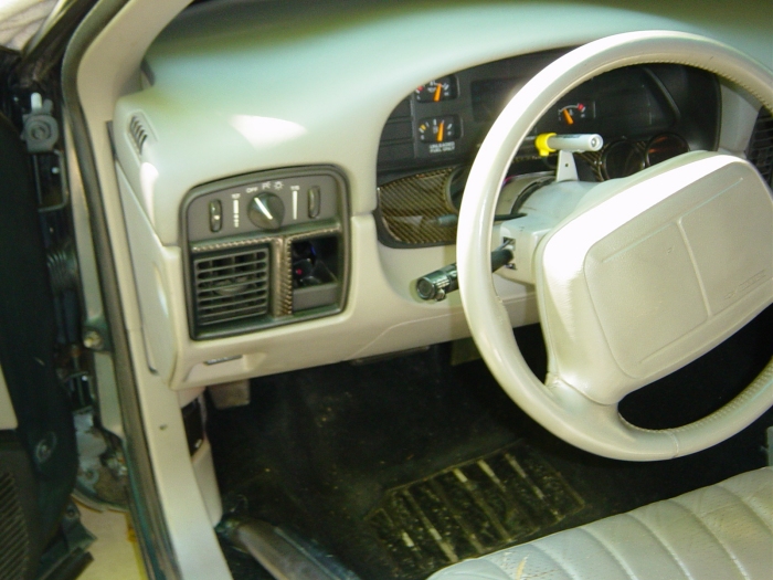
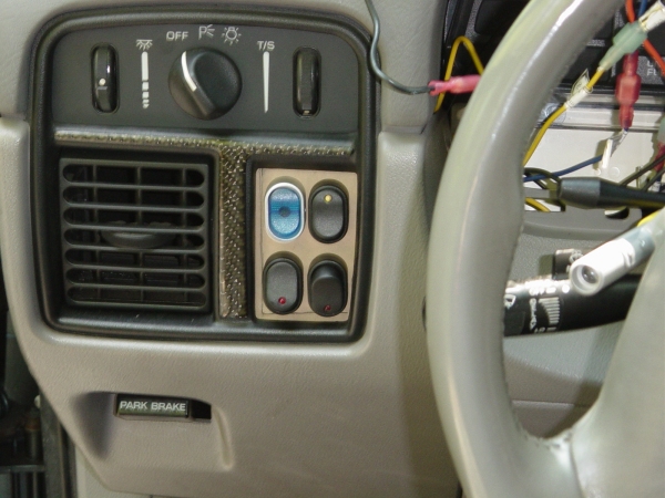
This panel has been sucesfully installed in a 1995 and a 1996 Chevy Impala SS. Since the interiors are identical in this area for the 1994 - 1996 Caprice and Impala SS it should fit any of these vehicles without problems.
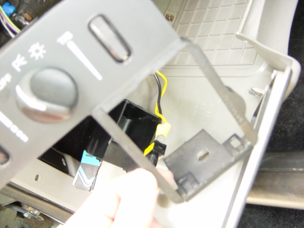
One concern that I had about this mod was in modifying the interior in such a way that it could not be undone. Perhaps it's just me being silly but I've done most of the mods to my SS with the thought that should there be a sudden increase in value on the SS or just some desire to revert the car to original, the mods could be removed, making the car, once again completely stock. With the exception of the four small holes to be drilled for support (which are completely hidden with the dash installed) there are NO modifications to the dash structure. If, in the future, you decide you want the coin tray back, it can be done with little headache.
I am open to constructive suggestions for improving this product. Please email me with idea's for improvement!
Thanks for visiting!
At this time, you have three options for purchasing the Coin Tray Switch Plate. All options include, insured, USPS shipping to the 50 states, an SEM (15243) satin black painted plexiglass plate, four screws and nuts for plate support and installation instructions.
The least expensive option, this is a non-drilled plate only. This option allows you to drill and install your choice of switches or other items, such as LED's, in a pattern of your choosing.
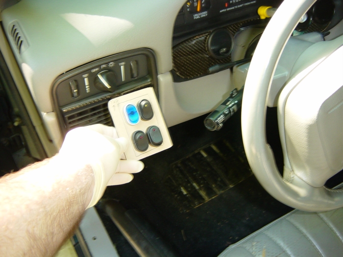
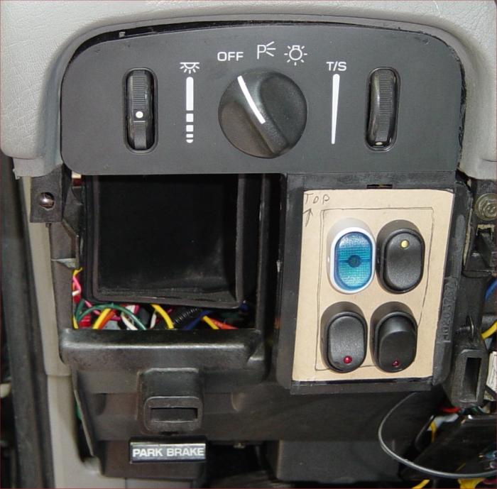
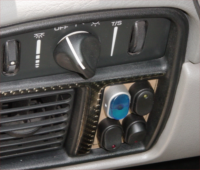
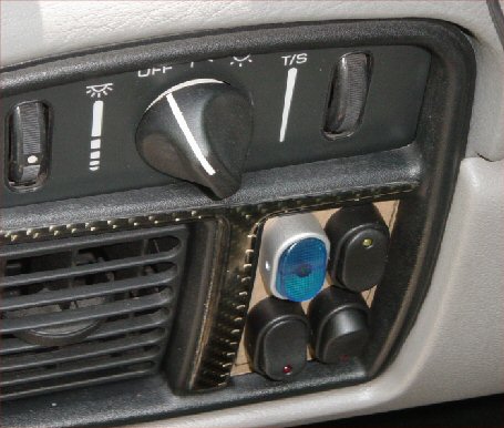
With this option, you will recieve a plate only drilled with four holes arranged in the pattern as shown in the photo above. I have tested rocker switches of the following brand and part numbers in the plate:
Conduct Tite! - 84842, 84840, 84871 - These switches I found at Advance Auto Parts.
Pilot - PL-SW22G, B, R (the last letter denotes the LED color) - I found these at Auto Zone.
Click here to see a picture of the packages
At this time, this is the most complete package available. In this package, you will receive the drilled plate as above with four black switches with LED status lights as pictured above. Unless otherwise specified during your order, your switches will be one each of Red, Green, Blue and Amber colored LED's. I am NOT including any wiring or connectors at this time simply due to the wide array of uses for this plate.
Please email me at gmcarnut@gmail.com to place an order. Let me know which option you would like and how you will be paying as well as any other comments or ordering instructions. Please also include your mailing address where I can send the plate.
Payment: I accept Personal Check, Money Order or PayPal for payment. I prefer the first two methods simply because PayPal charges me a fee for each transaction. If you pay by Personal Check, I will hold your order for 7 business days to ensure that the check has cleared.
Mail your payment to:
Michael Prosise
472 Fullerton Ln
Bentonville, VA 22610
or PayPal to:
gmcarnut@gmail.com
Shipping: This is not my full time job! However, I will endeavour to ship orders for option one and two within two days of payment. The kit's however, will take slightly longer as I do not keep a large stock of switches. I will make every attempt to have the kits shipped to you within not more than two to four days of payment.
Stupid Legal Disclaimer: By installing the switch panel you hereby release me (Michael Prosise) from any liability for problems with your vehicle or injury to self or others during or after installation of the switch panel.
Notes -
- There is a top and bottom to the switch plate if pre-drilled. Note the arrow I have made on the back pointing to the top of the plate. If you install the plate upside down, the switches will not be aligned and may not fit in the dash hole.
- I have left the protective paper on the back of the plates. You may remove this paper or not at your option, it will not show through the SEM paint on the front side.
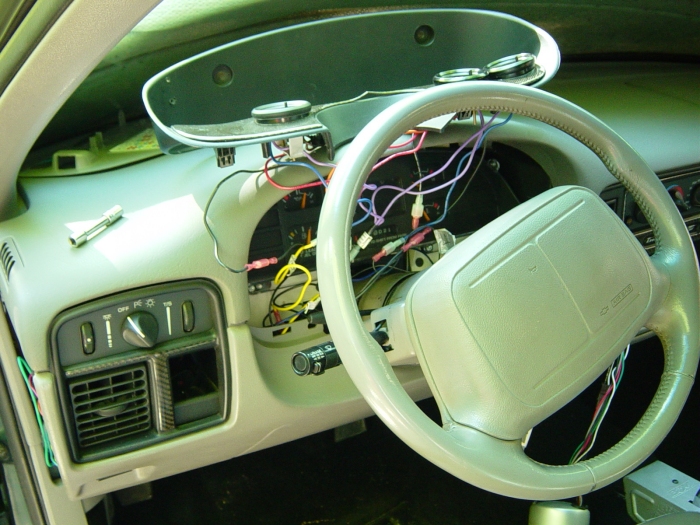
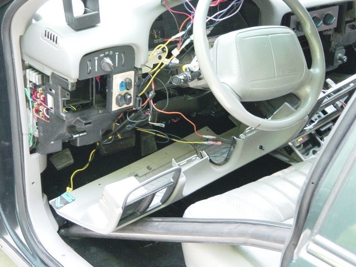
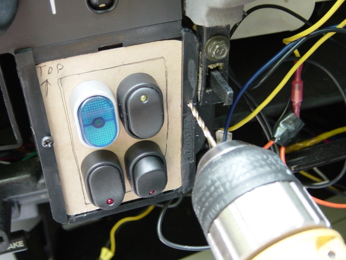
If you wish to use the included screws to hold the plate in place now is a good time to drill the holes for the screws. Use a 7/64 drill bit and drill four holes, two on each side through the dash plastic and the switch plate at the same time, this will ensure that your holes line up. You will have to hold the plate in place while drilling. BE CAREFUL NOT TO DRILL THROUGH YOUR HAND! Use light pressure on your drill as pressing too hard could crack the plastic switch plate.
If you decide to glue the plate in place, this should be done after all of your wiring is complete.
NOTE: I found a convenient place for a ground was to install a ring connector at one of the bolts holding the lower dash in place.
If using bolts, insert the bolts from the front side and hand tighten each one. You just need enough support here to keep the plate from moving when you press the switch buttons.
If gluing place glue on the left and right sides and press into the frame. Allow to dry for an appropriate amount of time.
|
I take this opportunity to thank the following people, without their help, this project would not have
been possible.
Mike Morgan (GOFASST) - Thank you for the idea to build this to begin with. Mike was kind enough to let
me take his idea and build a product.
Karl Ellwein (WAIL) - Karl took time from his busy schedule to take his car apart and test fit the prototype
for me as well as take photos along the way.
Matt Brame (Millbrook High School, VA) - Thank you for the use of your shop equipment and your time helping me
with the prototypes and templates.
© Copyright 2005 Michael Prosise. The materials contained on this site may not be duplicated, or reproduced without the express consent of the owner.
© All photographs are courtesy of and copyright, Karl Ellwein.
Email me to report broken links, page errors, etc.